
 11
11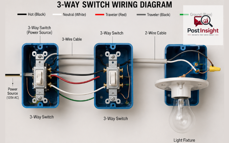
A 3 way switch wiring diagram shows how two separate switches can control one light from two different places. This setup is common in hallways, staircases, garages, large rooms, and entry areas where you may want to turn the same light on or off from either end.
In simple words, a 3-way switch circuit gives you two control points for one light. Instead of using one standard switch, the circuit uses two 3-way switches. These switches work together through traveler wires, a common wire, neutral wires, ground wires, and the final connection to the light fixture.
Before touching any electrical wiring, safety must come first. Always turn off power at the main breaker panel and test the wires with a voltage tester before working. The National Electrical Code is widely used as the safety standard for electrical installation, and local rules can vary, so checking local requirements or hiring a licensed electrician is always a smart choice.
| Part | Simple Meaning | Main Role |
| Common terminal | Usually the black screw | Connects power or load wire |
| Traveler wires | Usually red and black wires | Carry power between both switches |
| Neutral wire | Usually white wire | Completes the circuit at the light |
| Ground wire | Bare copper or green wire | Adds safety protection |
| Light fixture wire | Load wire | Sends switched power to the light |
A 3 way switch wiring diagram explains the path electricity follows between the power source, two switches, and the light fixture. It helps you see which wire connects to which terminal and why each connection matters.
The basic purpose of the diagram is to prevent confusion. A 3-way switch does not work like a normal single-pole switch. A regular switch simply opens or closes one hot wire. A 3-way switch changes the path of power between two traveler wires. That is why two switches can control the same light.
Wire placement matters because the circuit depends on the common terminals and traveler terminals being connected correctly. If the common wire is placed on a traveler screw, the light may not work properly. It may turn on from one switch but not the other, or it may behave in a confusing way. A clear diagram helps readers understand the layout before they begin.
A standard 3-way switch circuit includes two 3-way switches, one light fixture, cable between the boxes, and grounding connections. Each part has a clear job.
The 3-way switches are the main control devices. Each switch normally has one dark screw, two brass screws, and one green ground screw. The dark screw is the common terminal. The brass screws are for traveler wires. The green screw is for the ground wire.
The light fixture is the load. This means it is the part of the circuit that receives power and produces light. The fixture usually connects to a neutral wire, a hot/load wire, and a ground wire.
A 2-wire cable is often used to bring power into the first switch box or carry switched power to the light fixture. This cable usually has a black wire, a white wire, and a bare copper ground wire.
A 3-wire cable is usually used between the two switch boxes. It normally includes black, red, white, and bare copper ground wires. In many common 3-way layouts, the red and black wires work as travelers, while the white wire may carry neutral through the circuit, depending on the wiring setup.
Ground wires are very important for safety. They do not normally carry current during regular use, but they provide a safe path if something goes wrong. Ground wires should be connected to the switch ground screws and the light fixture grounding point.
One of the most important parts of a 3 way switch wiring diagram is the common terminal. On most 3-way switches, the common terminal is marked by a dark or black screw. This black screw is not the same as the black wire. It is a terminal location on the switch.
The common terminal has a different job depending on which switch box you are working in. In the first switch box, where power enters, the common terminal usually connects to the incoming hot wire. In the second switch box, near the light, the common terminal usually connects to the load wire that goes to the light fixture.
The traveler terminals are different. They connect the two switches together and allow power to move through one of two possible paths. These terminals are usually brass or bronze in color. The common terminal is important because it decides where power enters or leaves the switch system.
This is one of the main reasons people make mistakes with 3-way switches. They may connect wires by matching color only, but that can be risky. The screw position and terminal label matter more than wire color alone. Some switches also place the common screw in different locations, so always check the marking on the device.
Traveler wires are the wires that connect the two 3-way switches. In many home wiring setups, the red and black wires in the 3-wire cable are used as travelers. These wires allow the switches to change the path of electricity.
When one switch is flipped, it changes which traveler wire is connected to the common terminal. The second switch then completes or breaks the path to the light. This is why the light can be turned on or off from either location.
In many standard 3-way switch layouts, the traveler wires can usually connect to either brass screw. This means the red traveler and black traveler do not always need a fixed order on the brass terminals. However, both traveler wires must stay on the traveler terminals, not on the common terminal.
The traveler wires are the reason a 3-way circuit can feel confusing at first. A simple single switch only has one main switching path, but a 3-way system has two possible paths between the switches. Once you understand that the travelers are only linking the two switches, the wiring diagram becomes much easier to read.
A common setup is the 3-way switch wiring diagram power at switch layout. In this arrangement, the power source enters the first switch box. From there, the circuit continues through the second switch box and then to the light fixture.
In the first switch box, the incoming hot wire usually connects to the common terminal on the first 3-way switch. This is often the black wire from the power cable. The neutral wire does not connect to the switch. Instead, it is usually joined to the neutral wire that continues through the cable toward the light fixture.
The traveler wires from the 3-wire cable connect to the brass traveler screws on the first switch. These traveler wires then run to the second switch. In the second switch box, the same traveler wires connect to the brass traveler terminals of the second switch.
The load wire, which carries power to the light, connects to the common terminal on the second switch. This allows the second switch to send power to the light fixture depending on the position of both switches.
This type of diagram is often easier to understand than some other layouts because power begins at the first switch box. It gives a clean path: power source, first switch, traveler cable, second switch, and light fixture.
A 3-way switch wiring diagram with 3 wires usually refers to the cable running between the two switch boxes. This cable often contains black, red, white, and ground wires. Even though it is called “3-wire cable,” the bare ground is not usually counted as one of the main insulated wires.
The black and red wires are commonly used as travelers. The white wire may be used to carry neutral through the circuit, especially in a setup where power enters the first switch box and the light comes after the second switch box. The bare copper wire is used for grounding.
A simple layout works like this: power enters the first switch box, the hot wire connects to the common terminal, the traveler wires run between the switches, and the load wire from the second switch goes to the light. The neutral wire passes through the switch boxes and connects to the light fixture neutral.
This is why the white neutral wire should not automatically be attached to the switch. In many standard 3-way switch circuits, the switch controls the hot side of the circuit, not the neutral side. The neutral is usually joined through with a wire connector and continues to the light.
A 3-way switch wiring diagram power at light is different because the power source enters at the light fixture box instead of the first switch box. This setup can be more confusing because the hot wire, neutral wire, switch loop, and traveler wires may all meet in different ways.
In this type of wiring, the light box may contain the incoming power cable and cables going to the switches. Depending on the age of the wiring and the method used, a white wire may sometimes be re-identified and used as a hot conductor. That is one reason this layout needs extra care.
The main difference is the location of the power source. When power starts at the switch, the path is usually easier to follow. When power starts at the light, the diagram must clearly show how power is sent down to the switches and then returned to the light as switched power.
This setup is not something to guess through. If the wiring colors do not match a diagram, or if there are several cables in the light box, it is better to stop and get help from a qualified electrician. Wiring can vary by home, age, location, and previous repairs.
A simple 3 way switch wiring diagram can be understood by dividing the circuit into three areas: the first switch box, the second switch box, and the light fixture box.
In the first switch box, power comes in from the electrical panel. The bare copper ground wire from the power cable should be connected with the ground wire from the 3-wire cable and a short pigtail. The pigtail connects to the green ground screw on the first switch.
The white neutral wire from the incoming power cable is usually joined to the white wire in the 3-wire cable using a wire connector. These neutral wires do not attach to the 3-way switch in a basic mechanical switch setup. The black hot wire from the incoming power cable connects to the dark common screw on the first switch. The red and black traveler wires from the 3-wire cable connect to the two brass traveler screws.
In the second switch box, the bare ground wire from the 3-wire cable connects with the ground wire from the cable going to the light and another pigtail. That pigtail connects to the green ground screw on the second switch.
The white neutral wire from the 3-wire cable joins directly to the white wire going to the light fixture. The black wire going to the light fixture connects to the dark common screw on the second switch. The red and black traveler wires from the 3-wire cable connect to the two brass traveler terminals on the second switch.
At the light fixture box, the ground wire connects to the fixture ground screw or green lead. The white neutral wire connects to the fixture neutral connection, often the silver side or white lead. The black load wire connects to the fixture hot connection, often the brass side or black lead.
This layout is simple to follow when every wire is identified correctly. Still, never rely only on wire color if you are replacing an old switch. Always identify the common wire before removing the old switch, and take a clear photo before disconnecting anything.
Many homeowners search for a Leviton 3-way switch because Leviton is a common brand for residential switches, dimmers, and smart controls. The basic idea of a 3-way switch is the same, but the exact screw position can vary by model.
On a standard mechanical Leviton 3-way switch, you should look for the common terminal marking and the darker screw. Do not assume the common screw is in the same physical position as it was on the old switch. Different switch designs can place terminals in different spots.
Leviton’s own support material explains that a 3-way switch can control one light or appliance from two locations, and it also advises users to consult an electrician if they are unsure. Some Leviton installation documents also clearly state to turn off power at the circuit breaker or fuse before installation.
This is especially important with smart switches and dimmers. Some smart 3-way switches require a neutral wire, a matching remote switch, or a specific wiring method. A simple 3-way switch wiring diagram may not apply to every smart switch. Always read the model instructions before connecting wires.
A 3-way switch circuit controls one light from two locations. A 4-way switch circuit is used when you want to control the same light from three or more locations. This is common in long hallways, large rooms with several entrances, or staircases with multiple landings.
A 4-way switch wiring diagram includes two 3-way switches and at least one 4-way switch between them. The 3-way switches are placed at the two ends of the circuit, while the 4-way switch sits in the middle. If you need four control points, you can add more 4-way switches between the two 3-way switches.
The easiest way to remember the difference is this: two switch locations need two 3-way switches. Three or more switch locations need two 3-way switches plus one or more 4-way switches.
A 4-way circuit is more complex because there are more traveler connections. However, the basic purpose is the same. The switches control the path of power so the same light can be turned on or off from different places.
One of the most common mistakes in a 3-way switch circuit is mixing up the common wire and traveler wires. The common wire must go on the dark common screw. The travelers must go on the brass screws. If these are reversed, the light may not work correctly.
Another mistake is connecting the neutral wire directly to a basic 3-way mechanical switch. In many standard setups, the neutral passes through the box and continues to the light. It is not connected to the switch unless the device requires it, such as some smart switches.
Ignoring ground wires is also unsafe. The ground wires should be connected together and bonded to each switch and fixture as required. Grounding helps protect people and equipment if a fault occurs.
A very serious mistake is working without testing the wires first. Turning off the breaker is necessary, but you should still test before touching wires. Electrical testers and meters are used to check whether wires are hot and whether a circuit is safe to work on.
Another mistake is copying a diagram without checking your own wiring layout. Not every home is wired the same way. Some circuits have power at the switch, some have power at the light, and some may have older wiring methods. If anything looks different from the diagram, do not guess.
A 3-way switch wiring diagram PDF can be helpful because it gives you a clean visual guide to keep nearby while studying the circuit. A printable diagram is especially useful for beginners who want to understand the path before looking inside a switch box.
A good printable diagram should show the power source, first switch, second switch, traveler wires, common terminals, neutral path, ground wires, and light fixture connection. It should also label the black screw, brass traveler screws, and green ground screw.
The diagram should clearly show which wires are connected with wire connectors and which wires attach directly to switch terminals. It should also include safety reminders, such as turning off power, testing wires, checking local code, and calling an electrician if the wiring does not match the diagram.
A PDF guide should not replace proper electrical knowledge. It should be used as a learning tool, not as permission to work beyond your comfort level. If the switch box has extra wires, damaged insulation, aluminum wiring, no ground wire, or confusing colors, it is safer to get professional help.
A 3 way switch wiring diagram is useful because it makes a confusing circuit much easier to understand. It shows how two switches control one light, where the common terminals are located, how traveler wires connect both switches, and how the neutral, ground, and load wires complete the circuit.
The most important parts to understand are the black common screw, the brass traveler terminals, the neutral path, and the grounding connections. Once these parts are clear, the diagram becomes much less confusing.
Still, electrical work should always be handled carefully. Turn off power at the breaker, test wires before touching them, follow the device instructions, and check local requirements. If you are unsure about any wire or connection, hiring a licensed electrician is the safest choice. A good wiring diagram can guide your understanding, but safety should always come first.
A 3 way switch wiring diagram shows how two switches control one light. It explains the common wire, traveler wires, neutral wire, ground wire, and light fixture connections.
The black screw is the common terminal. It usually connects to the incoming hot wire on one switch and the load wire going to the light on the other switch.
Traveler wires are often red and black in a 3-wire cable, but wire colors can vary. Always check the circuit carefully instead of relying only on color.
You can understand the diagram yourself, but wiring should be done carefully. Always turn off power, test wires first, and hire a licensed electrician if unsure.
A 3-way wiring setup controls one light from two places. A 4-way wiring setup is used when you want to control one light from three or more places.
Disclaimer: This article is for general information only and is not a replacement for professional electrical advice. Always follow local electrical codes and hire a licensed electrician if you are unsure.